DMX / ArtNet Administration module
Introduction
DMX is a protocol that is traditionally used in stage and event technology. From small theaters to huge show stages, the lighting is realized via DMX. The light colors and the motorized axes of the head-moving headlights are usually controlled via DMX.
But of course there are many more devices and uses. For example, you can drop the curtain or start the fog machine using DMX triggering from NeuroomNet.
Due to the increasing popularity of LED light in permanent installations, there are also more and more applications in the home or corporate sector. Consider, for example, the indirect lighting in the conference room.
NeuroomNet connects DMX via network, i.e. uses the ArtNet protocol to communicate directly with DMX devices that understand ArtNet. Alternatively, you can use corresponding ArtNet-DMX interfaces.
Short introduction to DMX
DMX is a digital control protocol that is used in stage and event technology (event lighting) to control lighting technology such as dimmers, "intelligent" spotlights, moving heads and effects devices. The abbreviation DMX stands for Digital Multiplex (see Wikipedia).
With DMX, devices are connected via a special cable (serial or bus; there are no IP addresses or any form of routing) so that they can receive packets that contain 512 bytes each. These 512 bytes are also called channels. Each channel can therefore transmit 8 bits of digital information per package / package shipment. The devices are configured accordingly so that they know which channels are intended for them.
Fictional example:
Color spotlight A
- is switched on if Channel 0 has a value greater than 0 and
- then lights up in color from Channel 0, 1 and 2 (R, G and B)
Color spotlight B
- is switched on if Channel 3 has a value greater than 0 and
- then lights up in color from Channels 4, 5 and 6 (R, G and B)
Short introduction to ArtNet
Pure DMX is still very widespread, easy to understand and use, but has the limitation that only 512 channels or bytes of information can be transmitted (as specified in the digital control protocol).
ArtNet is based heavily on the DMX standard (in particular the basic idea with the 512 channels) and circumvents the restriction of 512 channels by allowing ArtNet to have not just one so-called universe with 512 channels, but several (depending on the ArtNet version up to 32768 universes with 512 channels each). In addition, the information of the universes and channels is no longer transmitted via a serial DMX bus, but via the UDP protocol in an intranet, which enables more targeted routing 1.
Newer devices that directly support ArtNet can be controlled directly via UDP and send the information required by the device about universes and their channels. Older devices are still connected to pure DMX bus networks and can be addressed via the DMX ArtNet interface, which is connected to the intranet and the respective DMX bus network (the interface then routes the information to the respective universe DMX bus network further into the DMX bus network).
For example, see the following links for further information about ArtNet and DMX
DMX and ArtNet in NeuroomNet
NeuroomNet can control ArtNet devices via the provider DMX2. This means that NeuroomNet controls DMX-ArtNet interfaces or devices that can be controlled directly by ArtNet.
Terminology DMX hardware and DMX components
In the real world we have
- DMX devices, which are connected to DMX networks (each of which represent a universe) via DMX cable
- ArtNet devices that are connected to an intranet via UDP
- DMX/ArtNet interfaces, which connect a DMX network to an intranet
These DMX/ArtNet devices from the real world are represented in the DMX/ArtNet Administration module by so-called DMX hardware with the following attributes:
- IP address: The fixed IP address of the DMX control device. IPv4 only.
- Start Channel: The first addressable channel in the ArtNet of the DMX control device. 0-indexed.
- Channel width: The number of addressable channels in the ArtNet of the DMX control device. This number is not tied to a universe (512 channels): every 512 channels, another universe (i.e. the next in ascending order) is automatically used.
- Start universe: The first addressable universe in the ArtNet of the DMX control device. This is basically an offset for the universe number calculated from the channel width.
- Name: Optional: For display purposes only. If not set, the IP address is used for display.
In contrast, DMX components are, so to speak, user-defined components with the following properties:
- appears in the hierarchy of the Setup module
- includes a list of DMX hardware
- can overwrite aspects of a DMX hardware
- has component actions that can be used to control the DMX hardware
Unlike most other providers/components, with components from the DMX provider there is generally no 1:1 relationship between components and DMX hardware or the actual hardware devices. Instead, there is an n:m relationship between DMX components and DMX devices, i.e. a component can address one to several DMX hardware and several components can also use the same DMX hardware (with different channels).
The DMX hardware is only visible and configurable in the DMX/ArtNet Administration module, while DMX components are also visible and usable in other modules such as the Setup module.
Configuration and use of DMX / ArtNet in NeuroomNet
In order to integrate DMX and ArtNet devices into NeuroomNet, it is best to first add the appropriate DMX hardware in the DMX / ArtNet Administration module. The second step is to create the DMX components in the DMX / ArtNet Administration module:
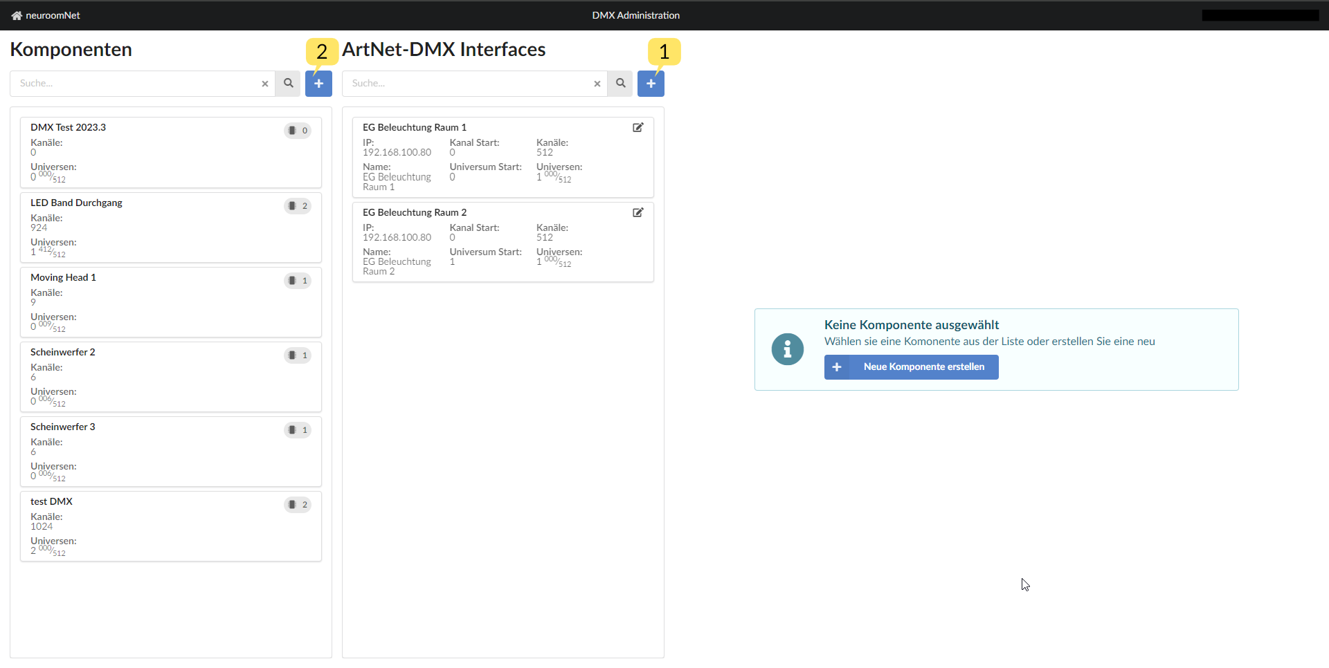
Note: DMX components can also be created in the Setup module, but there you are redirected to the DMX / ArtNet Administration module. DMX hardware can only be created in the DMX / ArtNet Administration module.
Create DMX hardware
To create new DMX hardware in NeuroomNet, click button 1 so that a popup opens where the in [Definition / Description DMX Hardware](#terminology-dmx-hardware -and-dmx-components) the data about the DMX hardware described above must be entered and confirmed with “Save”:
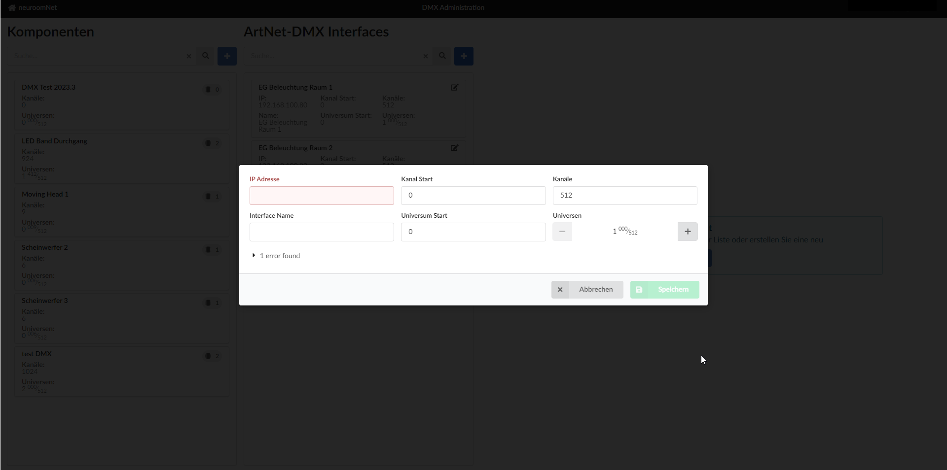
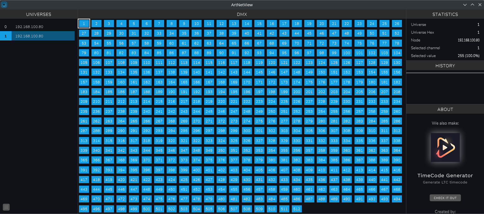
For testing purposes, the IP address can also be that of a computer running the software "ArtNetView".
Example:
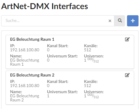
The hardware "EG Lighting Room 1" addresses an Artnet device with the IP address "192.168.100.80" and has 512 channels. This corresponds exactly to one universe.
For logical subdivision, the second universe with the same IP address can be created as a second hardware "EG lighting room 2". Normally, however, a hardware entry should correspond exactly to an ArtNet control device, which then contains, for example, 2 universes.
Create DMX components
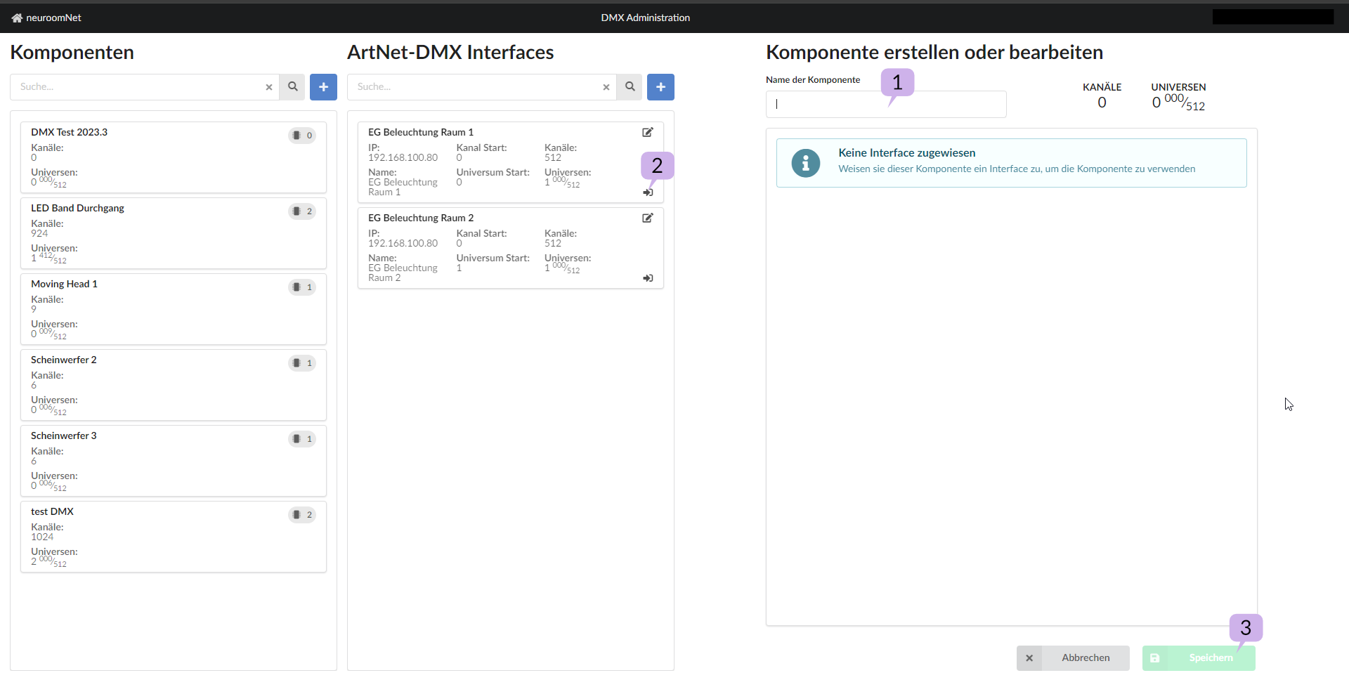
To create a new DMX component in NeuroomNet, click button 2 so that you
- can enter a name on the right side 1,
- can assign DMX hardware in the middle 2 and
- can confirm below with the "Save" button 3:
After clicking Save, the new DMX component is created accordingly:
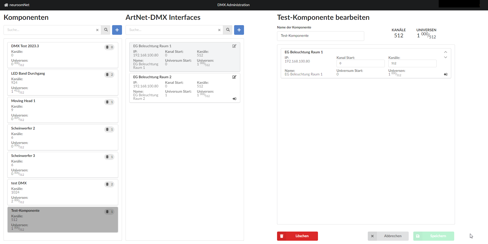
Using the component selected on the left, you can then set the universes and channels to be used for the component on the right (from the available area of the hardware).
Example 1: LED band
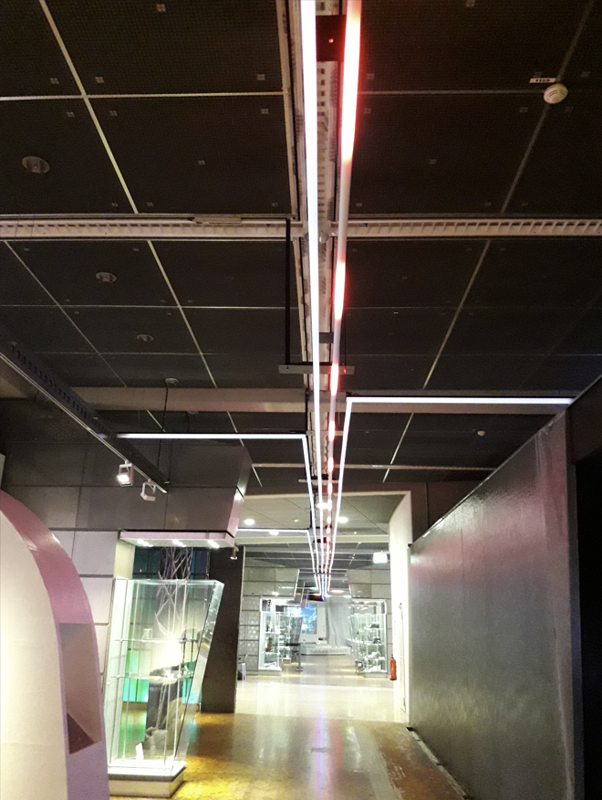
As a first example, let's consider a long LED strip that extends from room 1 to room 2:
Since in this example a different DMX-ArtNet interface is responsible for room 1 than for room 2, two DMX-ArtNet interfaces were assigned to the "LED band passage" component:
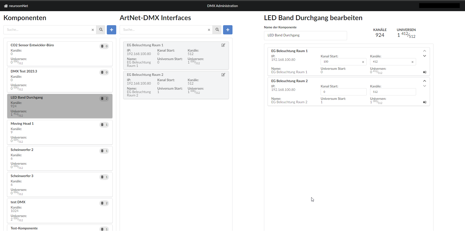
So the first channel of the DMX component is
IP: 192.168.100.80, Channel: 100, Universe: 0
and the last channel is
IP: 192.168.100.80, Channel: 511, Universe: 1
Example 2: Multiple spotlights
The other way around in this example 2 is not to address several DMX/ArtNet interfaces via one component, but rather to only address a subset of the available channels of a DMX-ArtNet interface:

In this example, the first spotlight is a moving head and uses nine DMX channels. Channel 1 is set as the start address. Moving Head 1 therefore occupies DMX channels 1-9, and each of these DMX channels can be used to control its own function of the moving head:
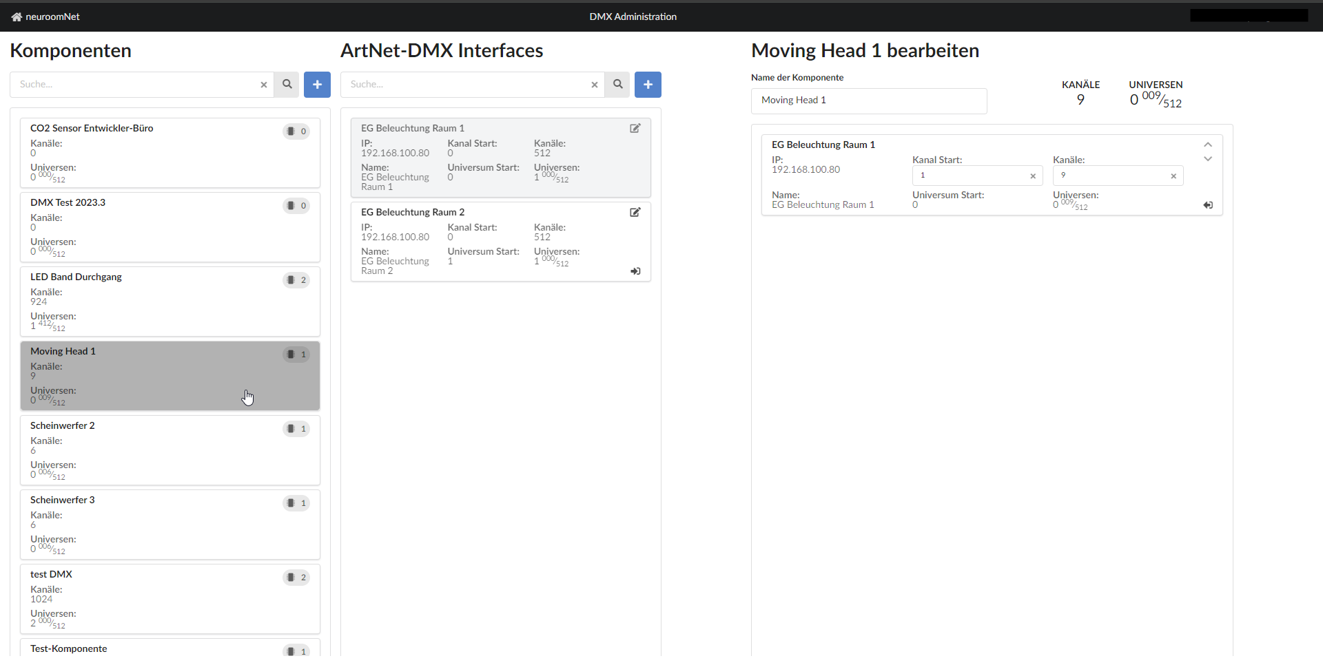
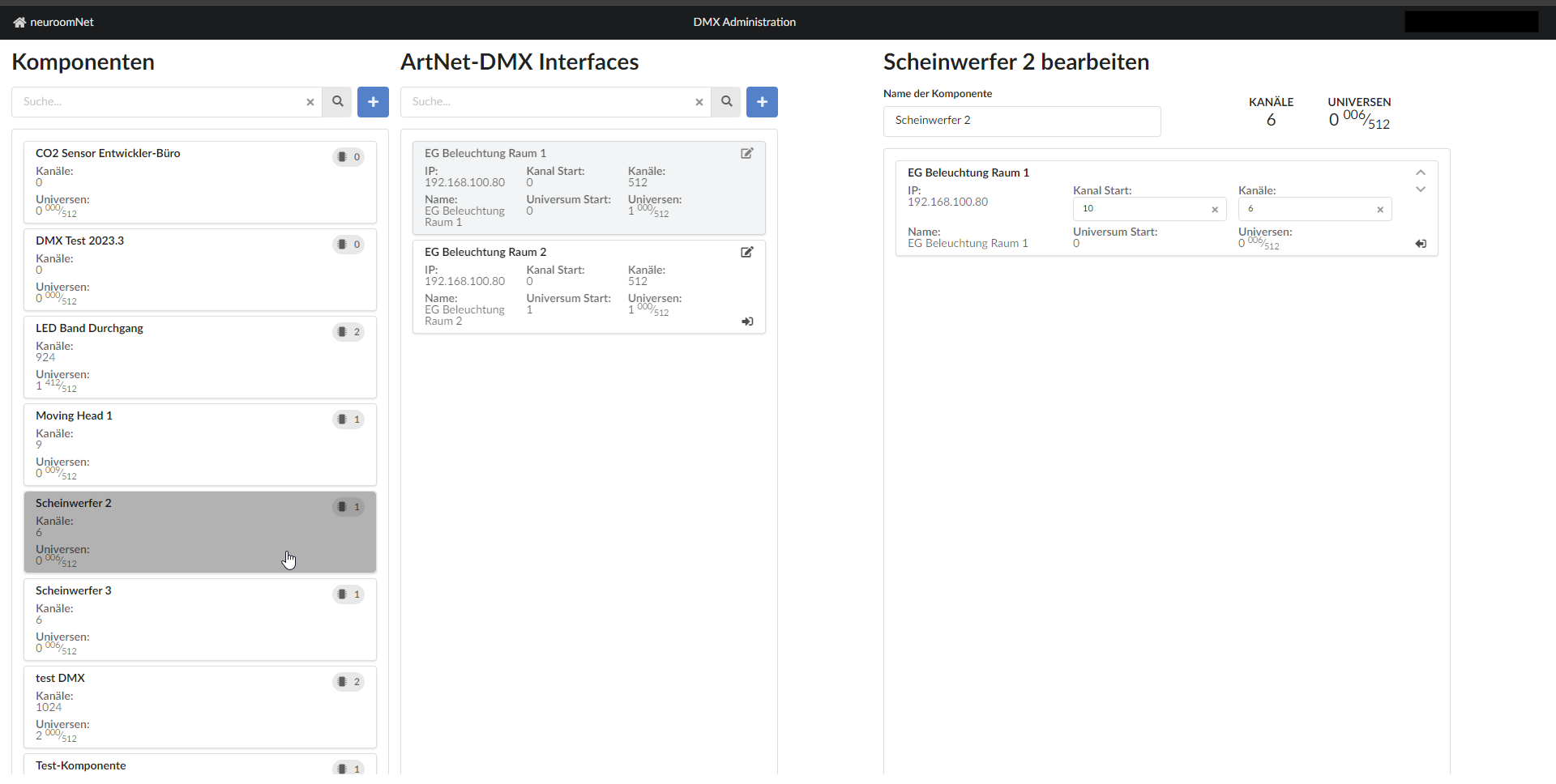
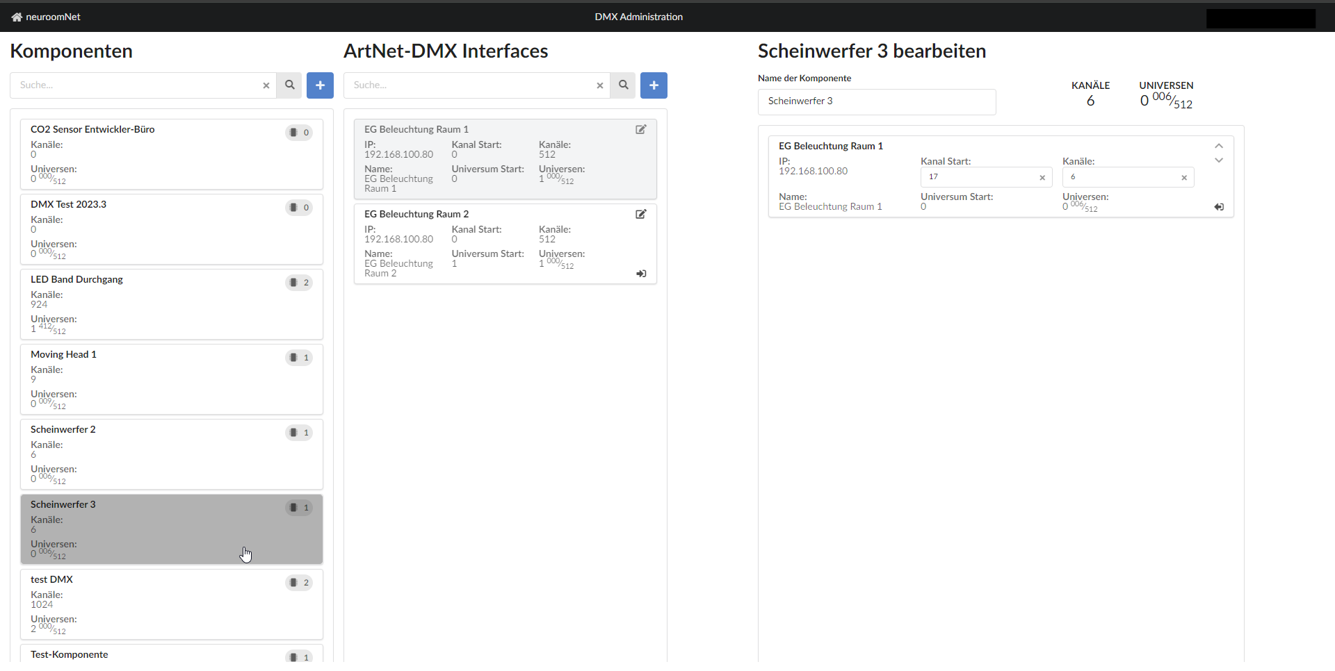
A subsequent spotlight would now have the start address 10 and, for example, occupy six DMX channels (10-16), a third with start address 17 would occupy channels 17-32 and so on:
Example action
If all channels of the "Headlight 2" component are to be set to 255 via the Setup module, then the associated action looks like this:
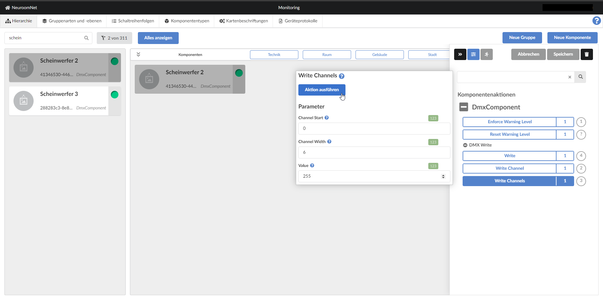
The available actions are further explained in the following chapter.
DMX actions of the components
The following actions are available for DMX components:
- Write Channel: Sets a single channel to a specific value.
- Channel: The channel to set.
- Value: The value to set. (0-255)
- Write Channels: Sets a range to a specific value.
- Channel Start: The first channel in the area to be set.
- Channel Width: The number of channels to set.
- Value: The value to set. (0-255)
- Write: (for advanced users) Sets a range to different values.
- Channel Start: The first channel in the area to be set. (Default: 0)
- Duration: How long the fade to the new value should take. In milliseconds. 0 sets the new value immediately. (Default: 0)
- Easing: Which easing function should be used for the fade to the new value. (Default: linear)
- Values: A list of new values. The values in the list can be either a number between 0 and 255, or two of these numbers. If a number is used, the previous value will fade to the new one. If two numbers are used, the first number fades to the second number. The list must be in the form of a JavaScript array:
[0, 100, [0, 255], 255]
Example of custom component type with aliases
Sometimes it makes sense to create a custom component type with aliases for certain DMX components:
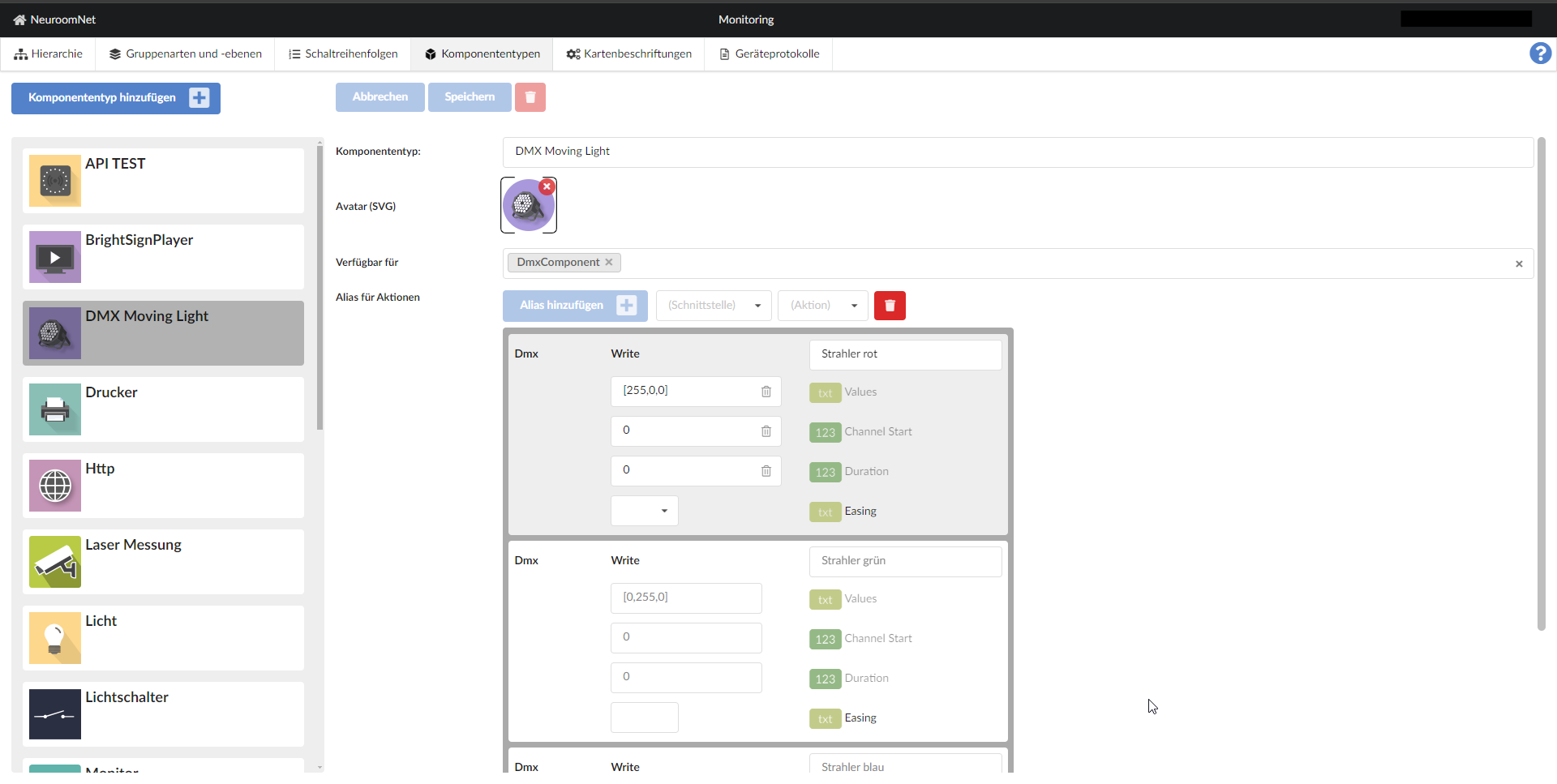
See Module Setup / Component Types Tab for more information about component types and aliases.
Example visualization / control of the result in ArtNetView
The software ArtNetView is recommended for testing and debugging purposes:
